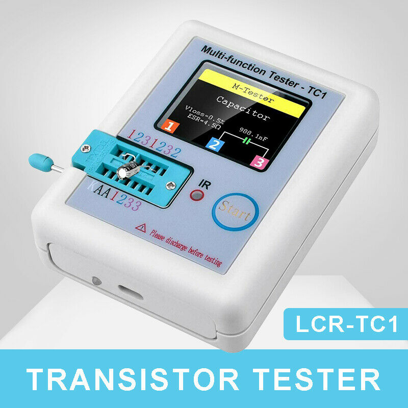
Digital Component Tester Transistor Diode Capacitor Inductor Resistor ESR Meter
Rated 4 out of 5 based on 4 customer ratings
$6.78
2330
Model:Multi-function Meter MPN:Does Not Apply Brand:Component Tester Refund will be given as:Money back or replacement (buyer's choice) Inductance:0.01mH - 20H Restocking Fee:No Country/Region of Manufacture:China EAN:Does not apply Capacitor:25pF-100000uF Return shipping will be paid by:Seller Item must be returned within:30 Days Condition:New All returns accepted:Returns Accepted Type:Capacitance or ESR Meter UPC:Does not apply Resistor:0.1ω-50Mω Measure Component:resistor/ diode/ capacitor/ transistors/ inductor Country//Region of Manufacture:China Product:LCR Meter
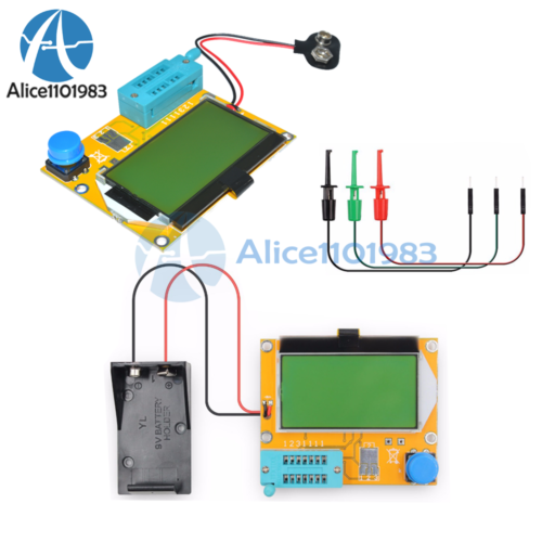
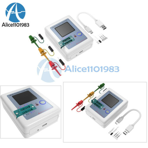
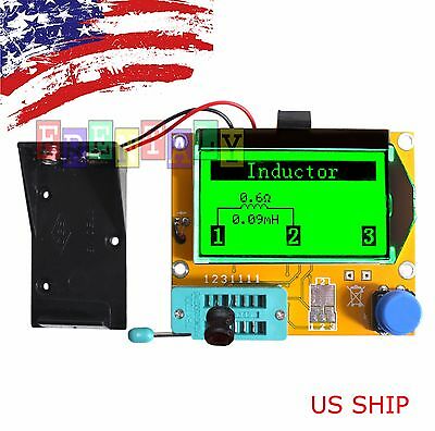
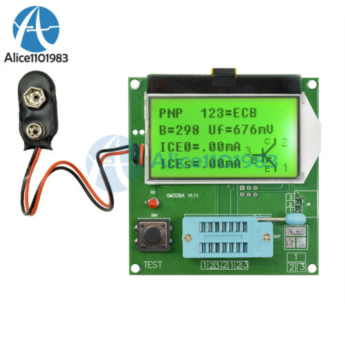
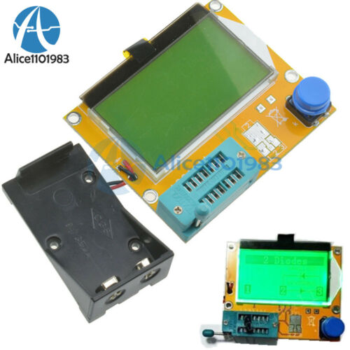
Welcome to Hello_Alian If you like this item, welcome to “Add to watch list” If you like our store, welcome to “+ Follow this seller” to follow us. You may also like, welcome use “Add to basket to buy” Description Welcome to my eBay store: hello_alian Tips: If you need large quantity, we can provide wholesales for you.Thanks. Specification : Feature: Easy and convenient to use. plug the component, click test button. the meter will measure and identify the component. Automatic identify components. Automatically detect the pins. Automatic measurement parameters As component meter can measure resistor/ diode/ capacitor/ transistors/ inductor Specification: Range Resistor: 0.1ω-50Mω Capacitor: 25pF-100000uF Inductance: 0.01mH – 20H Working power: DV-9V Standby current: 0.02uA Operating current: 25mA Notice: Before measuring big capacitor , the capacitor must be discharged , otherwise very likely damage the meter Package Include: 1 PCS x Component tester Not include battery (the airmail ban it, the battery type for the meter is 6F22(9v)) Test picture: Parameter for reference: 1.1 Operates with ATmega328 microcontrollers. 1.2 Displaying the results to a 128×64 graphic LCO-Display. 1.3 One key operation with automatic power shutdown. 1.4 Shutdown current is only about 20nA. 1.5 Automatic detection of NPN and PNP bipolar transistors, N- and P-Channel MOSFETs, JFETs, diodes, double diodes, Thyristors and Triacs. 1.6 Automatic detection of pin layout of the detected part. 1.7 Measuring of current ampli?cation factor and Base-Emitter threshold voltage of bipolar transistors. 1.8 Darlington transistors can be identi?ed by the threshold voltage and high current ampli?cation factor. 1.9 Detection of the protection diode of bipolar transistors and MOSFETs. 1.10 Measuring of the Gate threshold voltage and Gate capacity value of MOSFETs. 1.11 Up to two Resistors are measured and shown with symbols and values with up to four decimal digits in the right dimension. All symbols are surrounded by the probe numbers of the Tester (1-3). So Potentiometer can also be measured. If the Potentiometer is adjusted to one of its ends, the Tester cannot di?er the middle pin and the end pin. 1.12 Resolution of resistor measurement is now up to 0.01ohms, values up to 50M ohms are detected. 1.13 One capacitor can be detected and measured. It is shown with symbol and value with up to four decimal digits in the right dimension. The value can be from 2SpF to 100mF. The resolution can be up to 1pF . 1.14 For capacitors with a capacity value above 0.18pF the Equivalent Serial Resistance (ESR) is measured with a resolution of 0.01? and is shown with two significant decimal digits. 1.15 For capacitors with a capacity value above 5000pF the voltage loss after a load pulse can be determined. The voltage loss give a hint for the quality factorof the capacitor. 1.16 Up to two diodes are shown with symbol or symbol in correct order. Additionally the ?ux voltages are shown. 1.17 LED is detected as diode, the ?ux voltage is much higher than normal. Two-in-one LEDs are also detected as two diodes. 1.18 Zener-Diodes can be detected, if reverse break down Voltage is below 4.5V. These are shown as two diodes, you can identify this part only by the voltages. The outer probe numbers, which surround the diode symbols, are identical in this case. You can identify the real Anode of the diode only by the one with break down (threshold) Voltage nearby 700mV. 1.19 If more than 3 diode type parts are detected, the number of founded diodes is shown additionally to the fail message. This can only happen, if Diodes are attached to all three probes and at least one is a Z-Diode. In this case you should only connect two probes and start measurement again, one after the other 1.20 Measurement of the capacity value of a single diode in reverse direction. Bipolar Transistors can also be analysed, if you connect the Base and only one of Collector or Emitter. 1.21 Only one measurement is needed to ?nd out the connections of a bridge rectier 1.22 Capacitors with value below 25pF are usually not detectet. but can be measured together with a parallel diode or a parallel capacitor with at least 25pF. In this case you must subtract the capacity value of the parallel connected part. 1.23 For resistors below 2100? also the measurement of inductance will be done. The range will be from about 0.01mH to more than 20H, but the accuracy is not good. The measurement result is only shown with a single component connected. 1.24 Testing time is about two seconds, only capacity or inductance measurement can cause longer period. 1.25 Software can be configured to enable series of measurements before power will be shut down. 1.26 Selectable facility to calibrate the internal port resistance of port output and the zero o?set of capacity measurement with the selftest . A external capacitor with a value between 1OOnF and 20pF connected to pin 1 and pin 3 is necessary to compensate the o?set voltage of the analog comparator. This can reduce measurement errors of capacitors of up to 40pF. With the same capacitor a correction voltage to the internal reference voltage is found to adjust the gain for ADC measuring with the internal reference. 1.27 Display the Collector cuto? current ICEO with currentless base (10uA units) and Collector residual current ICES with base hold to emitter level . This values are only shown, if they are not zero (especially for Germanium transistors). 1.28 Thyristors and Triacs can only be detected, if the test current is above the holding current. Some Thyristors and Tnacs need as higher gate trigger current, than this Tester can deliver The available testing current is only about 6mA. Payment We only accept payment via Paypal. The buyer is responsible for any applicable import duties and local taxes. Usually there’s no any charges for small parcel. But please verify with your customs before making your purchase. Delivery details The items will be shipped within 1~2 working days after your payment is received and cleared.(excluding Saturday, Sunday & Holiday) All items will be shipped to your Paypal address, so please make sure to provide us with the correct, precise, detailed shipping address. The Delivered time to USA buyer is about 7~20 days, other country about 15~35 days delivered. Notes: Please contact us in advance if you need faster trackable or express shipping service. Terms of sales All the items will be tested before shipping. Buy them with the confidence! We maintain the excellent service standards and strive for 100% customer satisfaction and Positive feedback. If you have any problem, please do feel free to contact us before leave Neutral or Negative feedback, so that we can satisfactorily address your concerns. Return We afford all cost if it’s our fault. Exchange or refund. Contact us We strive to provide you with the best service, reply your question within 24 hours. Business time: 9:30~21:30 (GMT+8) exclude the weekend and holidays. Contact us